During the embedded programming week, we programmed our hello world with a code for the LED light and the button. However, we were very limited in what we could do on the hello world board with a 14 legs attiny 44, especially if we want to work with various sensors. The hello world board still requires an ISP even after burn bootloader. It also has limited pin headers for connecting sensor boards.
Objective:
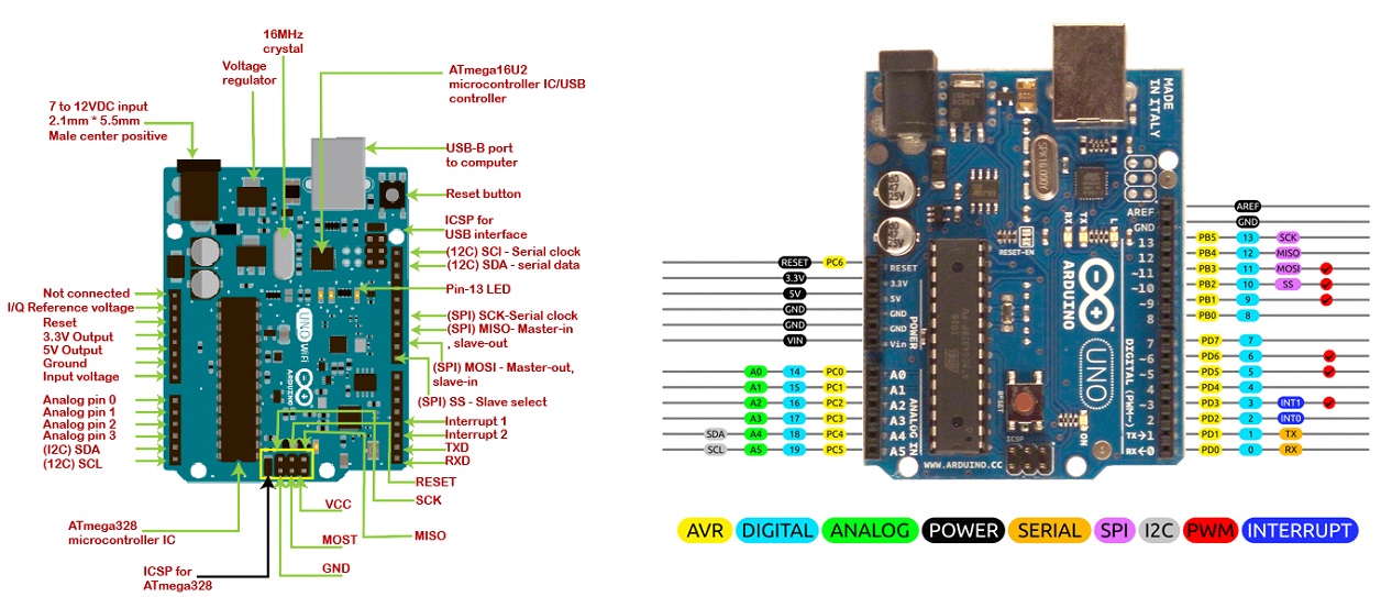
The goal of this week is to design a microcontroller board, add a sensor to it and read it. The board would need to be able to read sensor inputs, and eventually turning inputs into outputs. For example, reading a person in motion as input and outputing LED on; reading a person still as input and outputting LED off. An Arduino board is an existing board that would allow one to upload program onto its microcontroller, and reads digital or analog input and output. Here is the anatomy of a Arduino UNO board:
Arduino Uno Board & Pinouts
The Arduino UNO board contains the following components and specifications: ATmega328: This is the brain of the board in which the program is stored. Ground Pin: there are several ground pins incorporated on the board. PWM: the board contains 6 PWM pins. PWM stands for Pulse Width Modulation, using this process we can control the speed of the servo motor, DC motor, and brightness of the LED. Digital I/O Pins: there are 14 digital (0-13) I/O pins available on the board that can be connected with external electronic components. Analogue Pins: there are 6 analogue pins integrated on the board. These pins can read the analogue sensor and can convert it into a digital signal. AREF: It is an Analog Reference Pin used to set an external reference voltage. Reset Button: This button will reset the code loaded into the board. This button is useful when the board hangs up, pressing this button will take the entire board into an initial state. USB Interface: This interface is used to connect the board with the computer and to upload the Arduino sketches (Arduino Program is called a Sketch) DC Power Jack: This is used to power up the board with a power supply. Power LED: This is a power LED that lights up when the board is connected with the power source. Micro SD Card: The UNO board supports a micro SD card that allows the board to store more information. 3.3V: This pin is used to supply 3.3V power to your projects. 5V: This pin is used to supply 5V power to your projects. VIN: It is the input voltage applied to the UNO board. Voltage Regulator: The voltage regulator controls the voltage that goes into the board. SPI: The SPI stands for Serial Peripheral Interface. Four Pins 10(SS), 11(MOSI), 12(MISO), 13(SCK) are used for this communication. TX/RX: Pins TX and RX are used for serial communication. The TX is a transmit pin used to transmit the serial data while RX is a receive pin used to receive serial data.
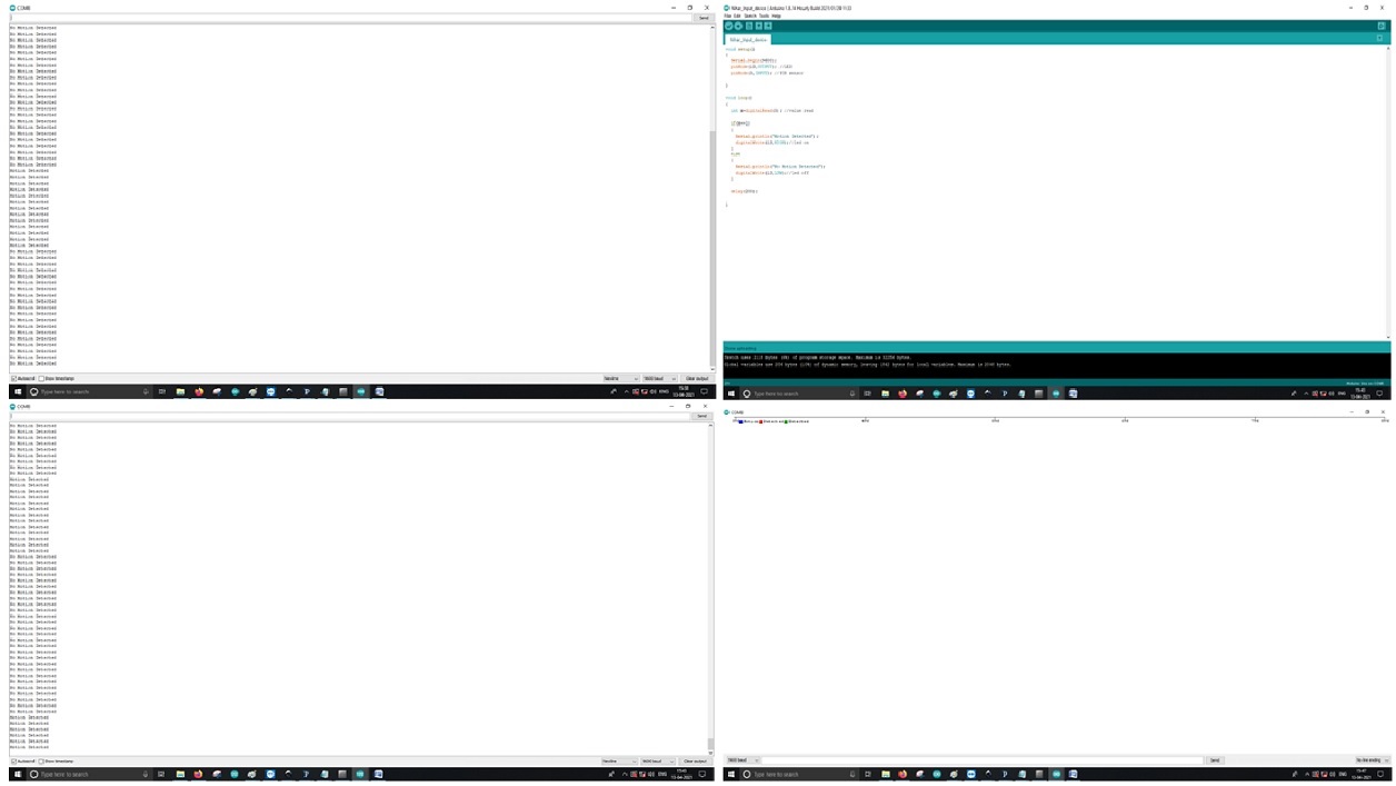
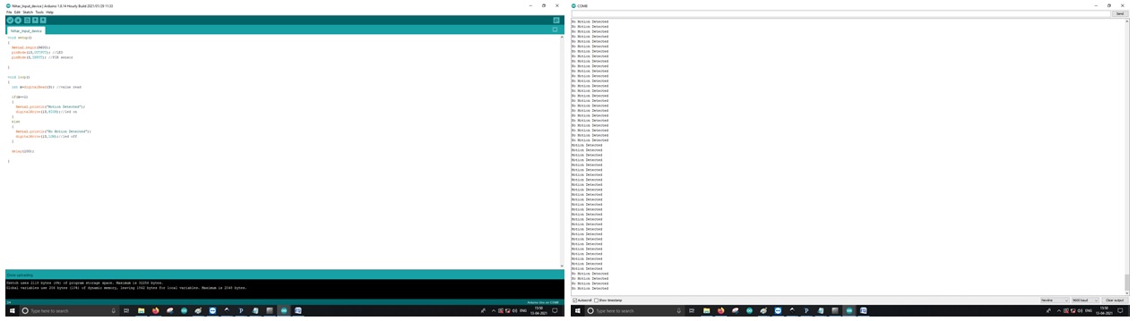
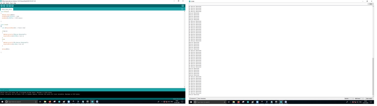
I learned how to use PIR; The PIR motion sensor is ideal to detect movement. PIR stand for “Passive Infrared”. Basically, the PIR motion sensor measures infrared light from objects in its field of view. So that, it can detect motion based on changes in infrared light in the environment. It is ideal to detect if a human has moved in or out of the sensor range. When motion is detected, the LED is turned on. If no motion is detected, the LED turns off.
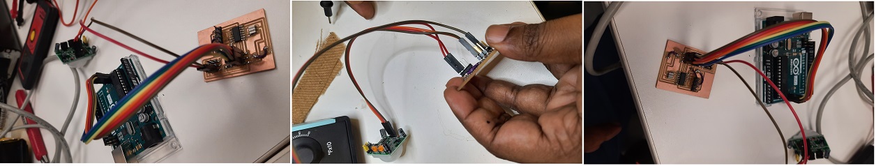
Wiring the PIR motion sensor to an Arduino is pretty straightforward – the sensor has only 3 pins.
GND – connect to ground
OUT – connect to an Arduino digital pin
5V – connect to 5V
Components used
Arduino UNO x1
Arduino PIR Module
LED (generic)
PIR Sensor (Most PIR sensors have a 3-pin connection at the side or bottom. One pin will be ground, another will be signal and the last pin will be power.)
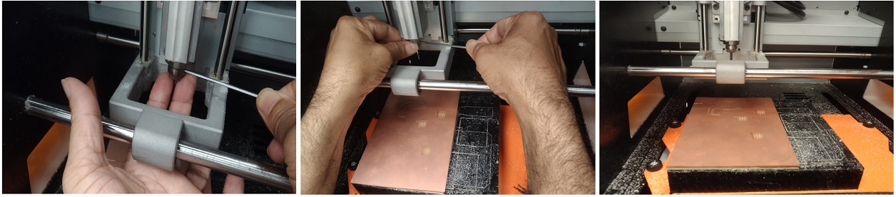
After that I downloaded the .rml file to the local system and through MODS, I uploaded the PNG file for set all the parameters for milling of the board.After that, I mounted the milling bit i.e 1/64 for trace and 1/32 for cut. During the installation of the milling bits we have to be careful by holding it in two finger else anything mishap may happen.
Then, I set to zero for x, y, and z for this Milling which will be a User-Friendly V-Panel. The SRM-20’s VPanel controller provides a simple interface for adjusting tool position and moving the cursor to set the milling starting point. The V-Panel also allows easy control of the feed rate and spindle speed with pause and resume operation, plus tracking of X,Y,Z axis milling with a numeric readout in millimeters or inches.
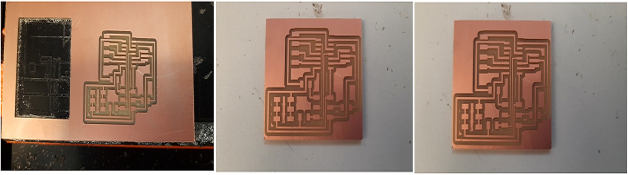
Milling of the circuit board
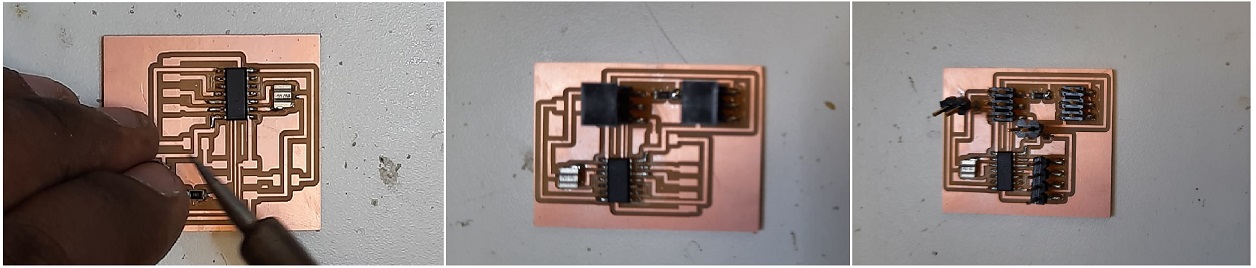
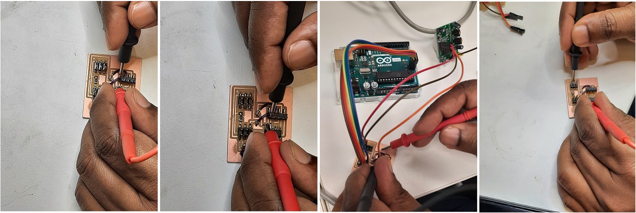
Soldering of the Circuit
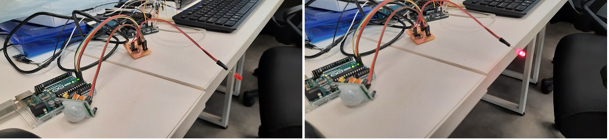
Testing the connection after soldering
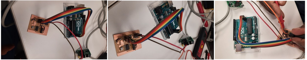
Quick Steps for final connection:
1. Connect Arduino to PC via USB cable
2. Open Arduino IDE, select the right board and port
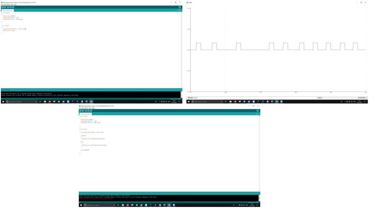
3. Copy the above code and open with Arduino IDE
Click upload button on Arduino IDE to upload code to Arduino